Reading time
3 Minutes
Architecture documentation with viewpoints: Best practice and normative aspects
Insight in Brief
This article shows which (auxiliary) means can be used to describe an architecture and how IMT implements this guideline in practice.
- Contrary to popular belief, a system or software architecture does not usually consist of “just one image”. In practice, several views are always required to describe an architecture.
- Viewpoints and views are a fundamental part of the international standard ISO/IEC/IEEE 42010. This article shows how IMT puts this guideline into practice.
Introduction
The documentation for system and software architectures is explicitly required for medical systems with safety-critical requirements, such as patient monitoring systems or ventilators. In addition, proof must be provided that an architecture has also been implemented according to its definition. But even outside the regulated area, the accurate description of an architecture is useful for most applications, because the description of an architecture is not only proof that requirements have been fulfilled, but it also helps to detect errors in the specification at an early stage. This article shows which (auxiliary) means can be used to describe an architecture and what can be followed.
Description of architecture
As explained in the article on system and software architecture, the architecture of a system is “the set of structures needed to infer the system or to ensure that the system satisfies the required properties. ”
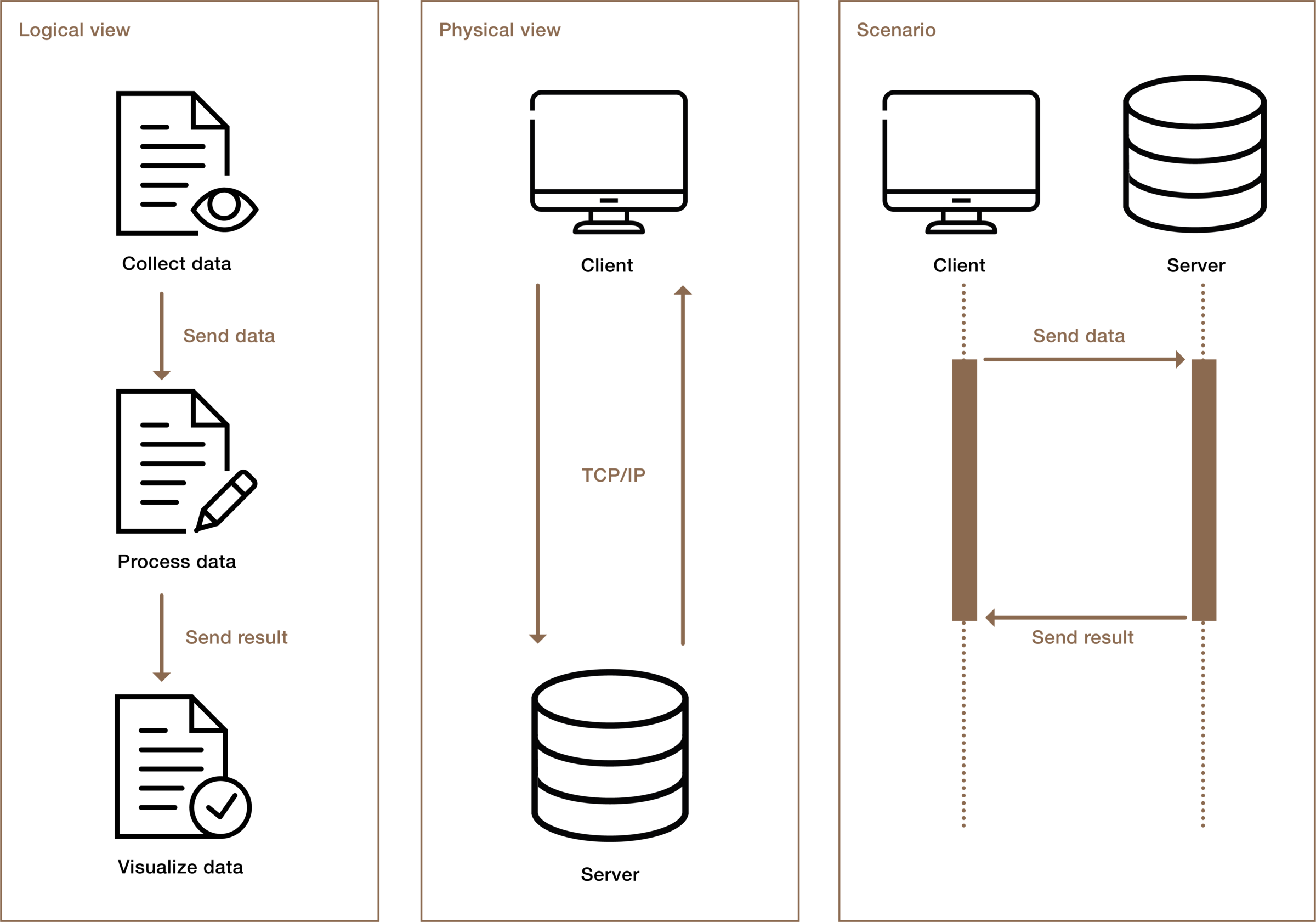
Admittedly, this definition is rather abstract and shows no concrete reference to hardware, electronics, or software. However, a system consists of different structures such as software, electronics, or mechanics. In addition, a system can also be characterized by logical structures or temporally sequential processes. In this sense, the term “architecture” can be misleading, as the singularity of the term architecture might suggest that architecture consists of a single image. However, practical experience shows that a system must be viewed from many different angles (views) and thus must also be described. For example, a system may be divided into logical units and functions that do not necessarily correspond to the physical division. This can be shown by the following, highly simplified, example:
But which is the right or best view, and most importantly, the one recognized by regulations?
As a rule, an architectural description consists precisely of showing different views, establishing connections between the views, and making clear the fulfillment of different requirements. In this respect, the description of architecture consists of several views, which illuminate different aspects. In other words, there is no one true view, but the description of an architecture takes equal account of different views (Basic Principle (II) of ISO 42010).
Views of architecture
The views are an essential part of the international ISO/IEC/IEEE 42010 standard, which provides guidance on how to describe the architecture of a system. This standard was published in 2011 and is the result of a joint ISO and IEEE revision of the earlier (software-heavy) IEEE 1471 standard. The original IEEE 1471 standard specified how to describe the architecture of a system. Further requirements, such as the structure of an architecture as well as requirements for description language, were added in 42010. However, the standard does not require a specific architecture description or description language. Instead, the practice of describing an architecture should be standardized.
Views are intended to represent a system by considering stakeholder requirements (concerns) based on defined viewpoints. Figure 2 shows how views, viewpoints, requirements, and stakeholders are related.

Due to IMT’s many years of experience in the field of system and software design, the following process has been established to create an architecture description, which is strongly based on the ISO 42010 standard:
- Identifying stakeholders
- Identifying description concerns/requirements
- Defining appropriate points of view (viewpoints)
- Creating views, based on the viewpoints
- Verifying the architecture using scenarios, repeating steps 4 and 5.
The individual steps are described in more detail in the following chapters.
Identifying stakeholders
In order to define the viewpoints in a targeted and, above all, systematic manner, the first step is to identify the stakeholders who work with and for the system, or make decisions about the system. These may include developers, product managers, risk managers, end users, production staff, project managers, etc.
Identifying stakeholders
The requirements for the architecture description should be recorded and documented based on the stakeholders identified. In addition to the context interview held with the stakeholders, information on requirements for architecture documentation can also be found in the user or system requirements. Table 1 shows how this might look using Figure 1 as an example.
| Stakeholder | Expectations of the architecture (concerns) |
| Software Developer | Definition of the target system(s)
Definition of interfaces
|
| Product Manager | Expected scalability
Proof of fail-safe operation |
| Data Protection Officer | Evidence of data protection |
Table 1: Identifying stakeholders and system-architecture expectations
Definition of appropriate points of view
The viewpoint is characterized by a set of requirements from the corresponding stakeholders, as well as different conventions regarding model types, notations, and techniques for the views based on them. Table 2 gives an example of how the viewpoints can be defined. The corresponding notations must be defined in addition to the tabular list. This can be done either in each view separately, or, in terms of the 42010 standard, in a separate viewpoint-specific section.
| Viewpoint | Concerns addressed | Model types | Analyze techniques |
| Logical
viewpoint |
Interfaces | Hierarchical decomposition diagram including description of all interfaces.
|
Reviews |
| Physical viewpoint | Scalability
Fail-safety Target systems
|
Hierarchical decomposition diagram including description of all interfaces.
|
Reviews
Fault tree analysis Scenarios |
| Data processing procedures
|
Data protection | Tabular list of data processing operations, including sensitivity classification and intended use. | Check-lists
|
| … | |||
Table 2: Definition of viewpoints
Viewpoints
A viewpoint is a type of template that can be (re)used across multiple systems and/or is interchangeable among architects. This template is then used to create system-specific views based on it. A well-known collection of viewpoints is the “4+1 view model” by Kruchen or the arc42 template, which are used in software systems especially. However, the use of viewpoints is not limited to software architectures—they can be applied to any system.
The definition and choice of viewpoints are primarily determined by the concerns of the identified stakeholders. In the following chapters, we present three possible views, although this set is not applicable to every system.
In general, it is recommended to keep the number of views used to a reasonable minimum, as redundancies increase with each additional view. In addition, each view must be maintained, tracked, and most importantly, kept consistent throughout the course of the project. The resulting effort increases with the number of views. In this case, less is more—provided that the views allow the requirements to be proven.
The logical view
The logical view is often used as the (primary) viewpoint for devices consisting of hardware and software. In the process, the system is broken down into its individual logical parts and arranged. In this view, functional requirements can be assigned to components, and possible functional redundancies within the system can be identified. Explicit assignment of system requirements makes sense, as this ensures traceability. Proof of traceability is required, especially for safety-critical systems. This applies not only to system architectures but also to subsystem and software architectures.
Communication paths and timing sequences/dependencies can also be defined within the logical view, depending on the architectural language. A combination is presented, as logical division and the associated processes are extremely dependent. Alternatively, the processes can be represented in a dedicated view, in which case the design of the logical view and process view is usually repetitive.
The physical view
As with the logical view, different physical viewpoints can expand the description and understanding of the system. Physical views can be, for example, electronic, pneumatic or electromechanical views, which are useful depending on the requirements of the system. A physical view can also make sense for distributed software systems, in which implementing non-functional requirements such as scalability, availability or performance can be demonstrated.
The development view
The development view is often only implicit, but it is also very important for a smooth project workflow. This shows how the system to be developed can be divided into small work packages in order to assign them to individual developers or development teams. Not only can internal requirements such as reusability or the selection of development tools be taken into account, but this view also enables development costs and deadlines to be monitored throughout the course of the project. The development view is often not part of the formal system architecture but is created as part of project planning.
Verification of architecture
Running scenarios is a popular tool for architecture verification. The most important key scenarios are defined depending on the requirements. A scenario is not a view in its own right but builds on existing views by linking them. Therefore, a complete architecture description is a basis for verification, or rather, the scenarios can only be run if the architecture has been fully described. Analogous to the description of the logical or physical view, the sequence of the scenario is presented in diagram form. Object interaction diagrams are often used to represent the interaction between logical and/or physical elements (see also Figure 1). Such scenarios are not only used to verify an architecture but also to help understand the structure of a system.
Practical example
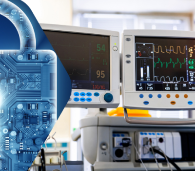
Citrex is a precise pressure and flow-measuring device designed for mobile use. Two microcontrollers are hidden inside. The measurement controller processes all sensor signals and performs sophisticated normalizations and compensations. The processed measurement signals are then transmitted to the UI controller, which displays the measured values on the graphical user interface and makes them available to the external interfaces (USB, serial).
The following stakeholder analysis was performed for the architecture description of the UI software:
| Stakeholder | Concerns |
| System Designer | · Fault tolerance concerns
· Interfaces to hardware modules · Risk classification according to 62304 · Persistent data · System States (Boot/Shut Down/Standby) · Update Procedure |
| SW Development Team | · Fault tolerance concerns
· Task, Interrupts and their connection · Risk classification according to 62304 · Interfaces to hardware modules · Persistent data · Deployment · Decomposition according to 62304 · System States (Boot/Shut Down/Standby) · SOUPs · Update Procedure · Project Planning/Monitoring |
| Signal Processing Development Team | · Task, Interrupts and their sampling rate
· Risk classification according to 62304 · Decomposition according to 62304 · Persistent data · System States (Boot/Shut Down/Standby) · Project Planning/Monitoring |
| Electronic Development Team | · Interfaces to hardware modules
· System States (Boot/Shut Down/Standby) · Update Procedure |
| Project Manager | · Fault tolerance concerns
· Interfaces to hardware modules · Risk classification according to 62304 · SOUPs · Decomposition according to 62304 · System States (Boot/Shut Down/Standby) · Update Procedure · Project Planning/Monitoring |
| QARA | · Fault tolerance concerns
· Risk classification according to 62304 · Decomposition according to 62304 · SOUPs · Decomposition |
| Auditors | · Risk classification according to 62304
· Decomposition according to 62304 · SOUPs |
| Imt Analytics | · SOUPs
· System States (Boot/Shut Down/Standby) · Risk classification according to 62304 · Project Planning/Monitoring |
Table 3: Identifying stakeholders and their concerns about the flux-measuring device Citrex
The next step was to define the different viewpoints in order to address the concerns accordingly. In this example, 7 viewpoints were sufficient to cover all expectations.
| Viewpoint | Concerns addressed | Modell-Type | Analyse techniques |
| Deployment & SOUP View | SOUPs
Deployment |
Euler diagram | Review |
| Risk classification View | Risk classification according to EN62304 | Euler diagram | Review |
| Dynamic/State View | System States (Boot/Shut Down/Standby)
Update Procedure Fault tolerance concerns |
State/Flowchart diagram | Sequence Diagrams
Review |
| Decomposition View | Decomposition according to 62304 | Tree diagram | Review |
| Process View | Persistent data
Task, Interrupts and their connection Sampling rates |
Data flow diagram | Sequence Diagrams
Review |
| Interface View | Interfaces to hardware modules | Data flow diagram | Review
Sequence Diagrams |
| Development View | Project Planning/Monitoring | Tree diagram / Lists / Burndown charts | Review |
Table 4: Definition of viewpoints for the UI software
Designing the software architecture and documenting it using views is a repetitive process. It is therefore unrealistic to expect the creation of different views to proceed in a linear fashion. However, a starting point is needed so that the repetition can begin at all. In practice, the top-down approach has proven successful in systematically disassembling and defining a system (or in this case software system) from “top” to “bottom”. Once the top-level structures are defined, individual items are systematically selected and documented with additional views. A good starting point is the Deployment View, where the essential software items and SOUPs (Software of Unknown Provenance) are defined. Figure 3 shows how this might look using the Citrex measuring device’s UI software as an example.

Since it is not yet clear from this view how the UIBootloader and UIFirmware programs are related and interact, a Dynamic/State view was also worked out at the top level, among other things. Table 5 shows an overview of all views created for the UI controller.
| System/Subsystem | Erstellte Views |
| UI Controller | Deployment & SOUP view (Abbildung 3)
Dynamic/State view Risk classification view Development View |
| UI.BootloaderUpdater | Decomposition view
Dynamic/State view Interface view |
| UI.Main | Decomposition view
Process view (Abbildung 4) Dynamic/State view Interface view |
Table 5: Views created for the UI controller for the purpose of architecture documentation.
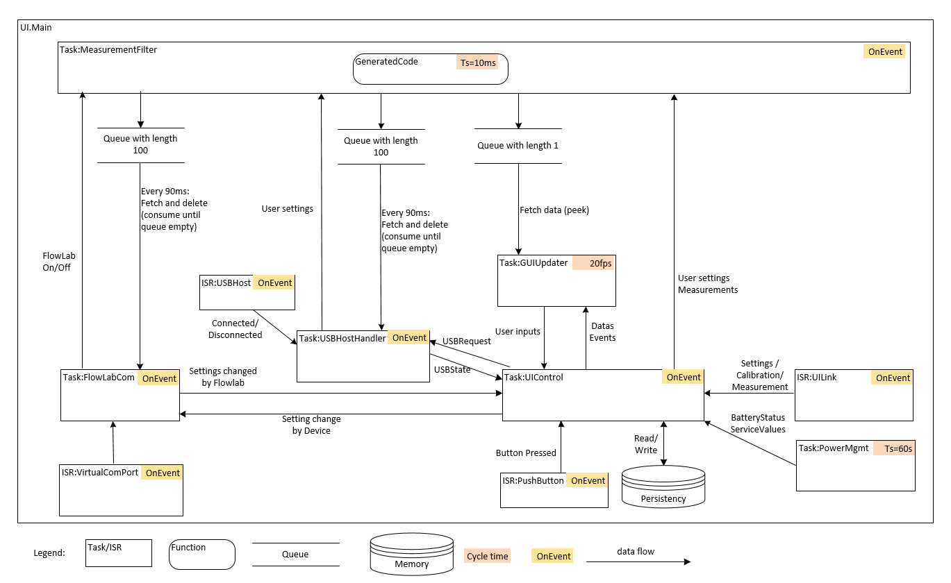
So, in total, 11 views were created based on 7 viewpoints. Four of them show the software system from a top-level view. The remaining 7 views are distributed among the software items UI.BootloaderUpdater and UI.Main defined in the deployment view. Figure 4 shows an example of the process view of the UI.Main software item.
However, our work is not yet done with design views. Fundamentally, each view contains a listing and description of all components and their drivers (e.g.: system requirements). Furthermore, the creation of architecture documentation includes further steps, such as verification by means of scenarios, listing of constraints (limitations that influence the architecture), justifications of architecture decisions, and explanations of the integration and test strategy. The best way to do this is described in this article. A total of 9 scenarios were defined and run through for the UI controller. Figure 5 shows the scenario of how the measurement value gets from the measurement controller to the GUI.

Summary
Often, different stakeholders are involved who place different demands on a system. In order to address these concerns specifically and to verify that they have been fulfilled, several views are needed to describe an architecture. These views can be derived from generally defined viewpoints. The viewpoints consist of universally applicable conventions and are thus interchangeable and reusable across multiple systems. Finally, an architecture description can be verified with the help of scenarios to demonstrate fulfillment of the most important requirements.
Share


More Expert Blog articles
Discover IMT’s engineering expertise and innovative solutions in our Expert Blog. Gain valuable know-how from our experts and explore technology highlights.