Reading time
6 Minutes
Flow Sensor Design Without Endless Prototypes: FSI Simulation in Practice
Designing flow sensors for ventilators with deformable elements involves complex physical interactions between fluid dynamics and structural mechanics. Traditional development approaches rely heavily on iterative prototyping.
This is especially challenging when injection-molded components introduce long lead times. Fluid-Structure Interaction (FSI) simulation offers a powerful alternative, enabling engineers to predict sensor characteristics early in the design process, reduce iteration cycles with physical prototypes, and gain deeper insight into the underlying physics.
In this article, IMT shows in a reverse-engineering project how a combination of FSI simulation, simplified structural models and measurements can shorten your development
Insight in Brief
- FSI simulation enables accurate prediction of flow-induced deformation in sensor components
- Coupled CFD and structural models reveal pressure distribution and flap behavior
- Simulation results correlate well with experimental measurements
- Simplified mechanical models can support early-stage design decisions
- Design insights include sensitivity to flap geometry
- Simulations reduce reliance on costly and time-intensive prototyping cycles
Introduction
Flow sensors with deformable elements, such as the shown flap-based designs, are widely used due to their robustness and simplicity. However, their performance depends on a tightly coupled interaction between fluid flow and structural deformation. Capturing this behavior during development is challenging, particularly when relying solely on empirical testing.
In a reverse-engineering project of a legacy flow sensor (Proximal Flow Sensor), IMT investigated how advanced Fluid-Structure Interaction (FSI) simulation can support and accelerate the design process. The goal was also to validate the simulation results against experimental data and to assess what kind of insight FSI can provide during development.
From Legacy Design to Simulation-Driven Understanding
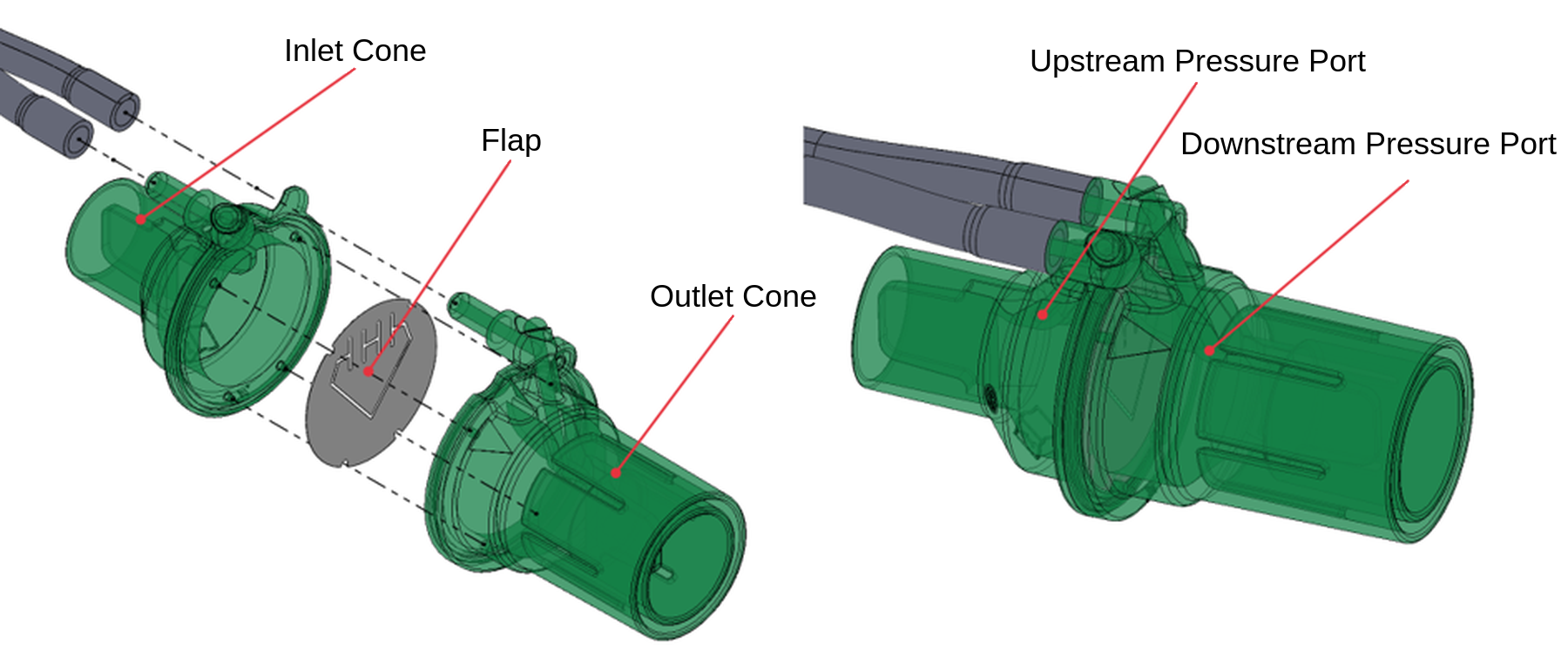
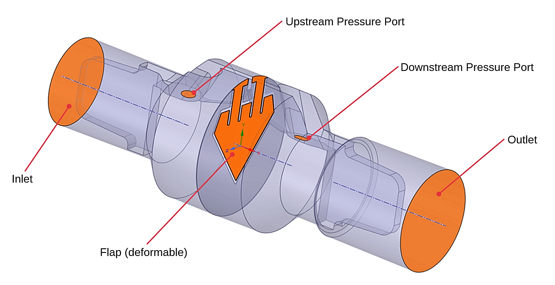
The iFlow sensor consists of two housing components (Inlet Cone and Outlet Cone) enclosing a deformable plastic flap. As flow passes through the device, the flap deflects, creating a specific relationship between flow rate and pressure drop across the two measurement ports.
This characteristic curve is highly sensitive to:
- Flap geometry (e.g. shape, thickness)
- Material properties (e.g. stiffness of the flap)
- Mounting conditions
- Flow-induced pressure distribution
Traditionally, optimizing such parameters requires multiple iterations in prototypes which are particularly costly and time intense when tooling for injection-molded parts is involved.
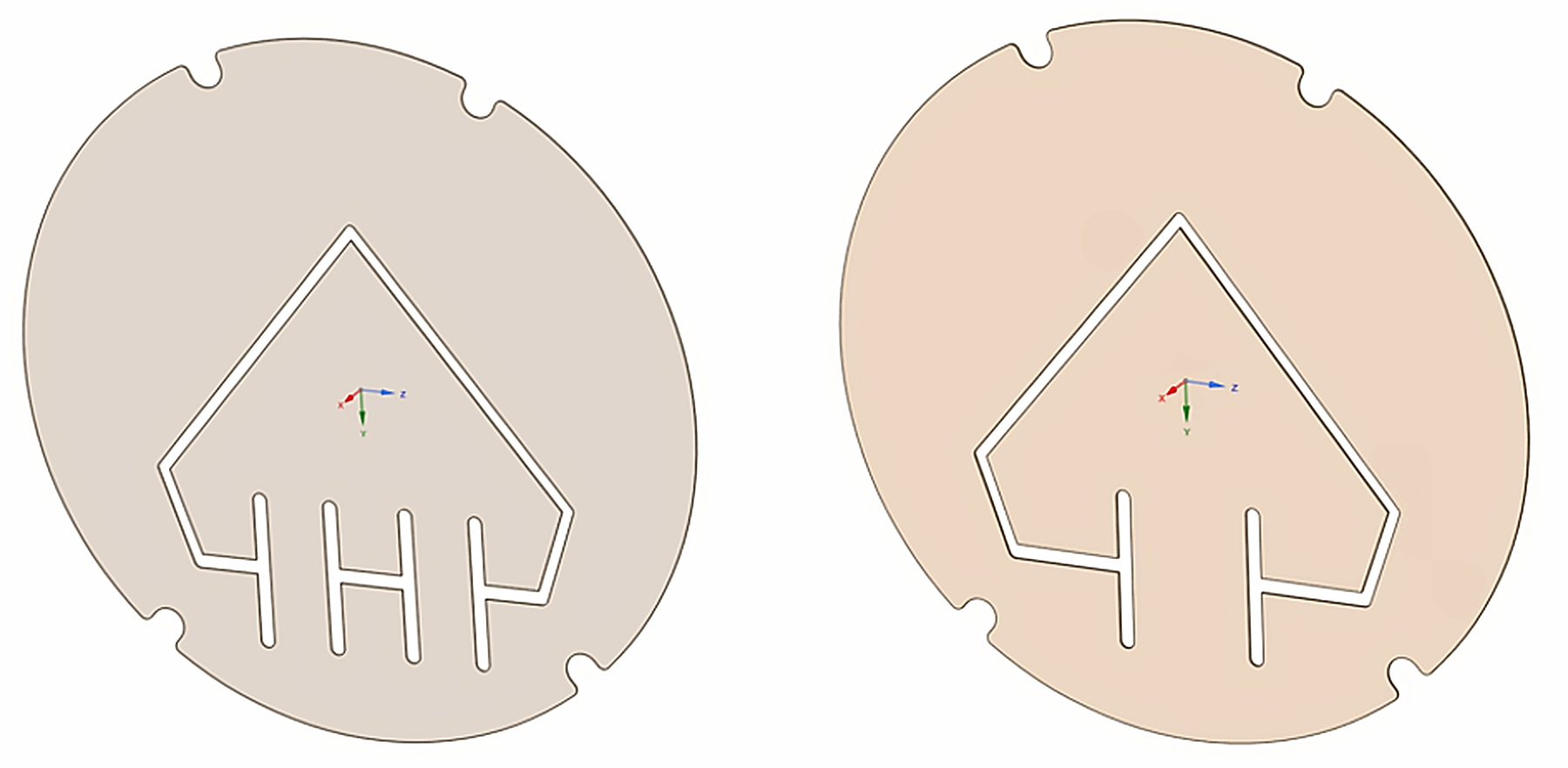
In this study we simulated two different geometries of the flap. The first geometry has two legs, and the second geometry has one leg. The total width of the two-leg design is the same as the width of the one leg design.
FSI Simulation Setup and Methodology
To capture the coupled physics, a two-way Fluid-Structure Interaction (FSI) simulation was implemented using ANSYS Workbench with System Coupling. The fluid domain was modeled in ANSYS Fluent, while the structural response of the flap was computed in ANSYS Mechanical.
A tetrahedral mesh with dynamic remeshing was applied to the fluid domain to accurately resolve deformation-induced changes in the flow field. The simulation setup incorporates a fully coupled interaction between fluid pressure and structural deformation, ensuring that both domains influence each other throughout the solution process.
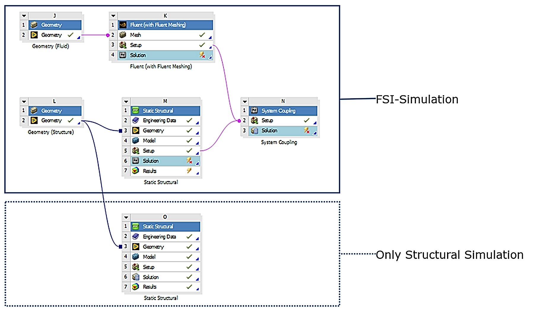
A steady-state simulation approach was chosen to represent a defined operating condition of the sensor. The relevant boundary conditions of the simulation are shown in Figure 4. Due to the high computational effort associated with such simulations, the analysis was focused on one representative design point, with an inlet pressure of approximately 40 Pa
Validation: Simulation vs. Measurement
A critical outcome of the study was the agreement between simulation results and experimental measurements. The FSI model reproduced the resulting pressure–flow characteristics accurately enough (less than 5 % difference to measurements).
The pressure at the inlet of the sensor (constant inlet pressure of 40 Pa as boundary condition) is slightly higher than the pressure at the measurement ports of around 32 Pa. This can be expected because of the additional pressure drop created by the flow straighteners.
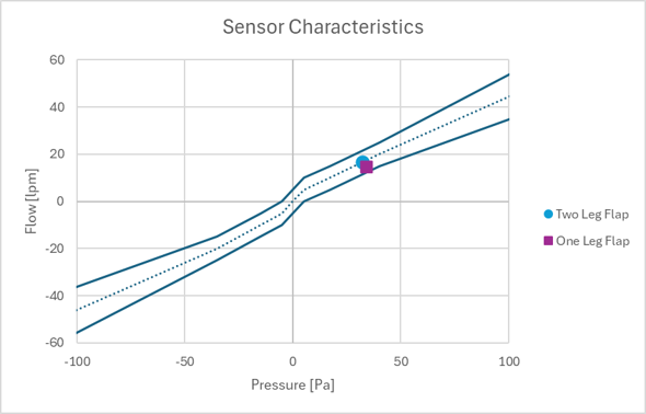
The FSI model reproduced the resulting pressure-flow characteristics accurately enough (less than 5 % difference to measurements).
Comparing two different geometries of the flap, we see differences in the characteristics.
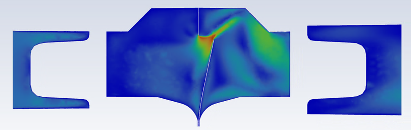
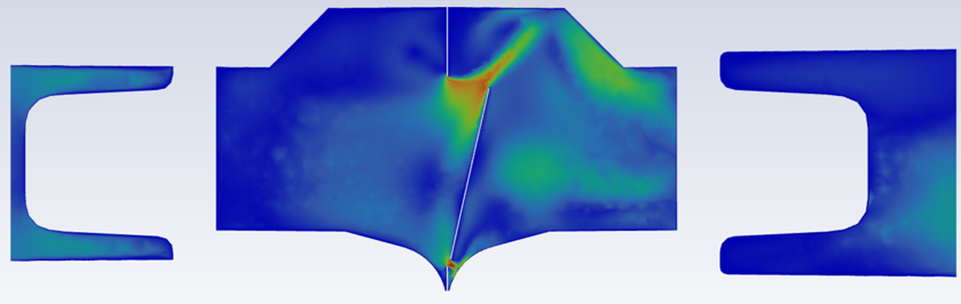
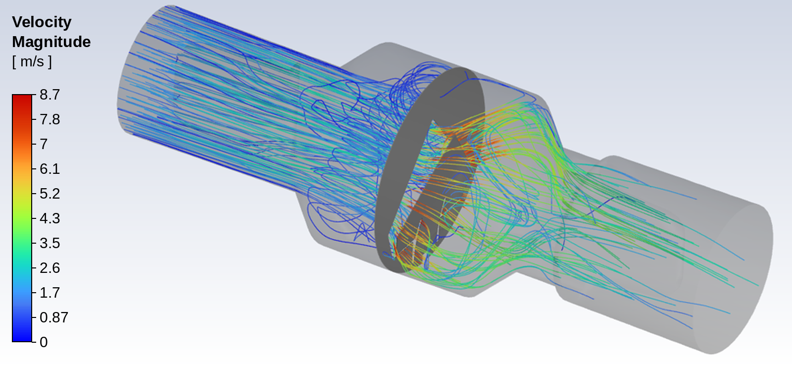
The Proximal Flow Sensor uses a two-leg flap design, and we can see that the pressure and flow of this design is on the nominal characteristic (dashed line, see figure 5). The One Leg Flap (see figure 6) has lower displacement at the top which results in a smaller opening area and thus a higher pressure drop and lower flow than the two-leg design (see figure 7).
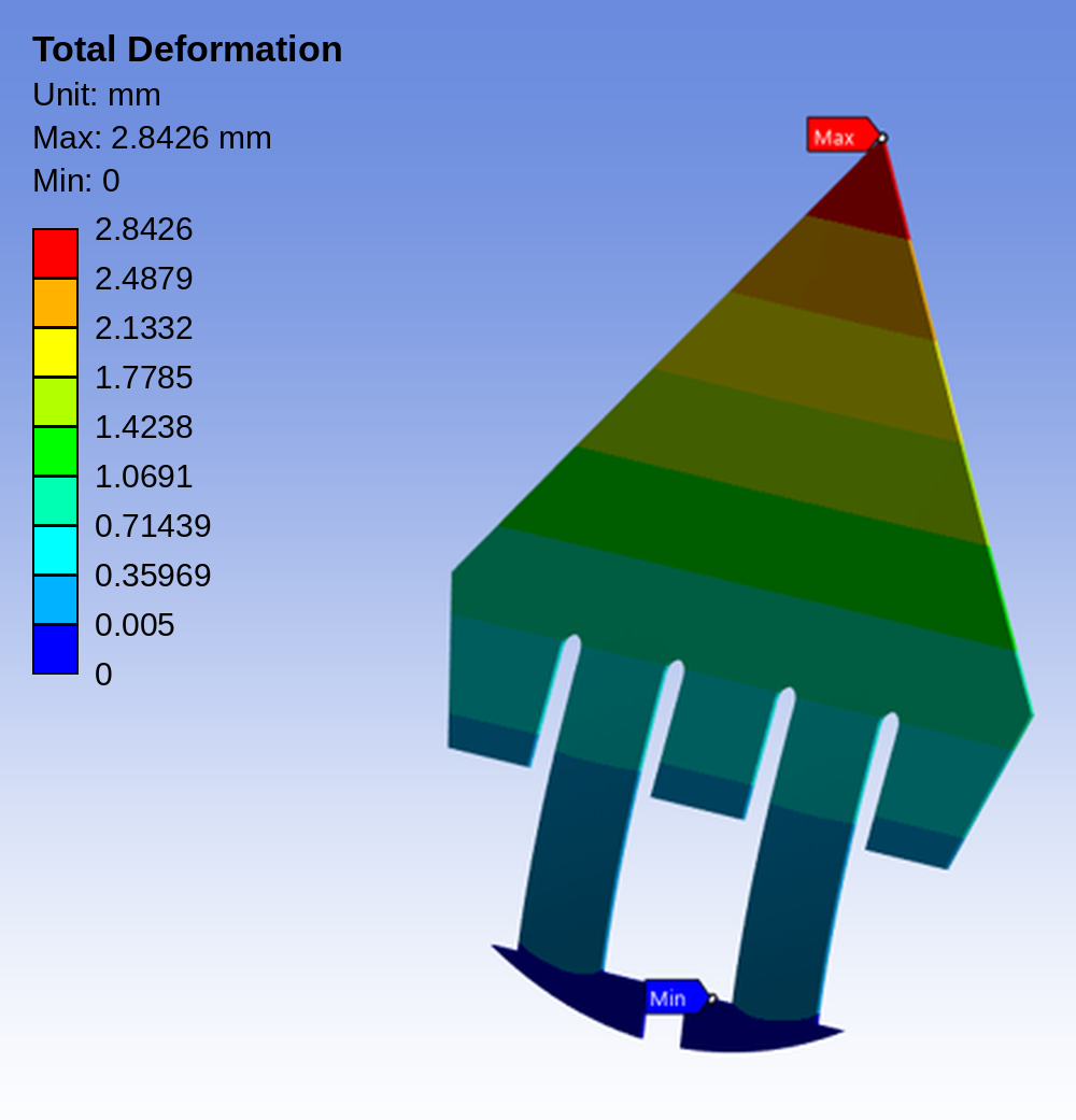
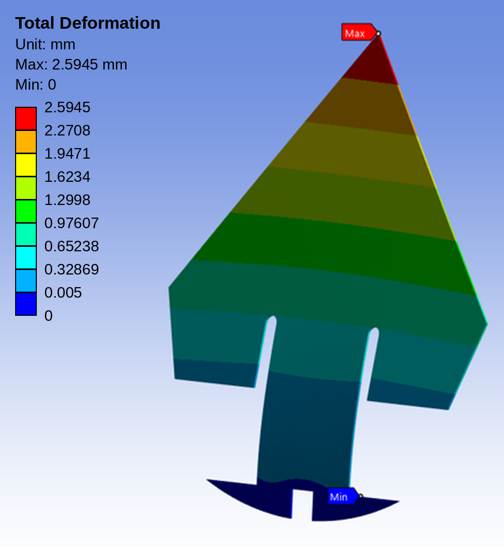
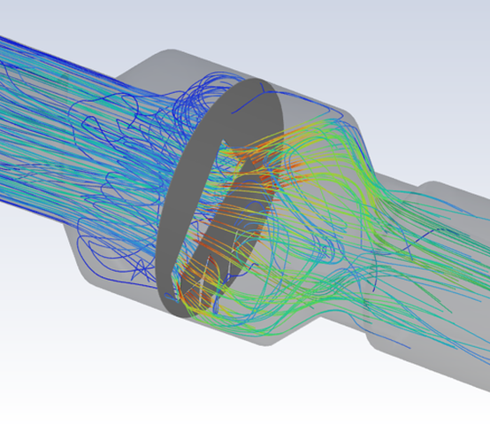
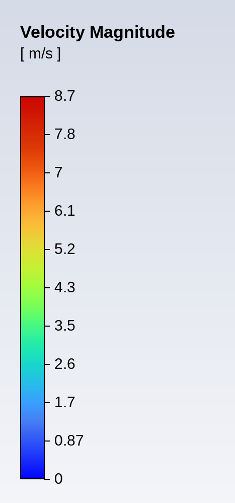
Looking at the velocity magnitude distribution of two flap geometries, the simulation shows that changing the flap support from a single-leg to a two-leg design affects flap displacement (increase of 0.25 mm displacement in two leg flap) and the surrounding flow field. In a similar way as the changed displacement, these differences directly influence the pressure drop and sensor characteristic.
Key Design Insights from FSI Simulation
Pressure Distribution and Simplification Potential
The FSI simulation revealed that pressure distribution on the flap is not perfectly uniform. At the tip of the flap and at the edges, slightly lower pressures can be observed. However, at an inlet pressure of approximately 40 Pa, the effective load can be conservatively approximated as a uniform pressure resulting in higher displacements and loads on the flap.


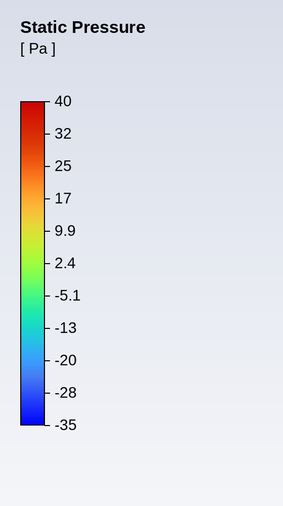
Figure 9: Pressure Distribution on the two leg flap in FSI-Simulation
This enables a key simplification: Early-stage design iterations can rely on pure structural simulations using a uniform pressure load, significantly reducing computational effort. Many more design variants can thus easily be evaluated and only the most interesting ones are examined in more detail in an FSI simulation or in a physical prototype.
When looking at the displacement between FSI simulation and purely structural simulation in figure 10, there is a difference in the maximal displacement of around 0.87 mm. Thus, results from only structural simulation shall be used for comparing variants and not for absolute values of the flap in the actual application.
Early-stage design interations can rely on pure structural simulations using a uniform pressure load, significantly reducing computational effort.
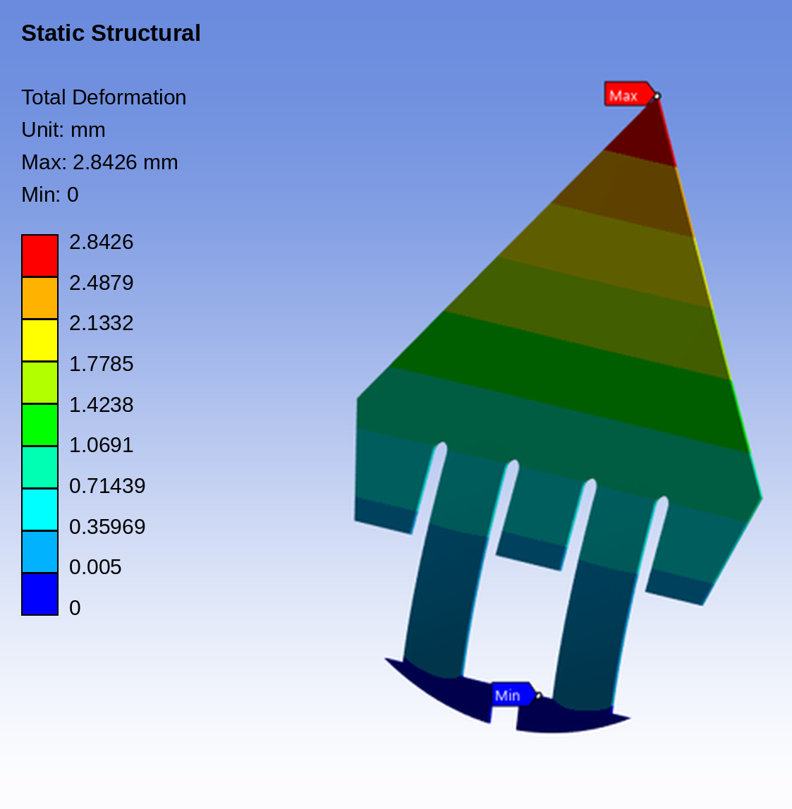
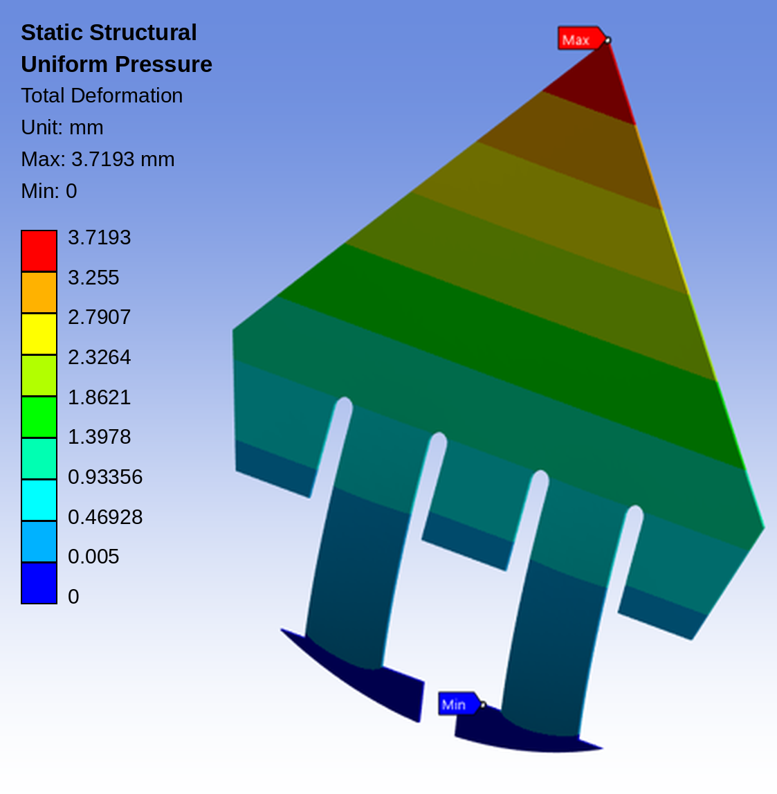
Figure 10: Comparing deformation in FSI Simulation (left) to deformation in purely structural simulation (right)
Sensitivity to Flap Geometry
One of the most impactful findings was the strong influence of the flap geometry at the base. The tip displacement is clearly influenced if the whole flap or only the deformable part of the flap attached by the legs is considered, see also figure 11.
These two different geometries resulted in:
- Significant variation in tip displacement
- Corresponding changes in sensor characteristics
This highlights that even small geometric modifications can drastically alter performance. Such behavior can efficiently be evaluated in purely structural simulations.
In an FSI simulation, the deformable area shall be kept as small as possible for a computationally efficient simulation, and we can use the gained input from the structural analysis for making a suitable choice.
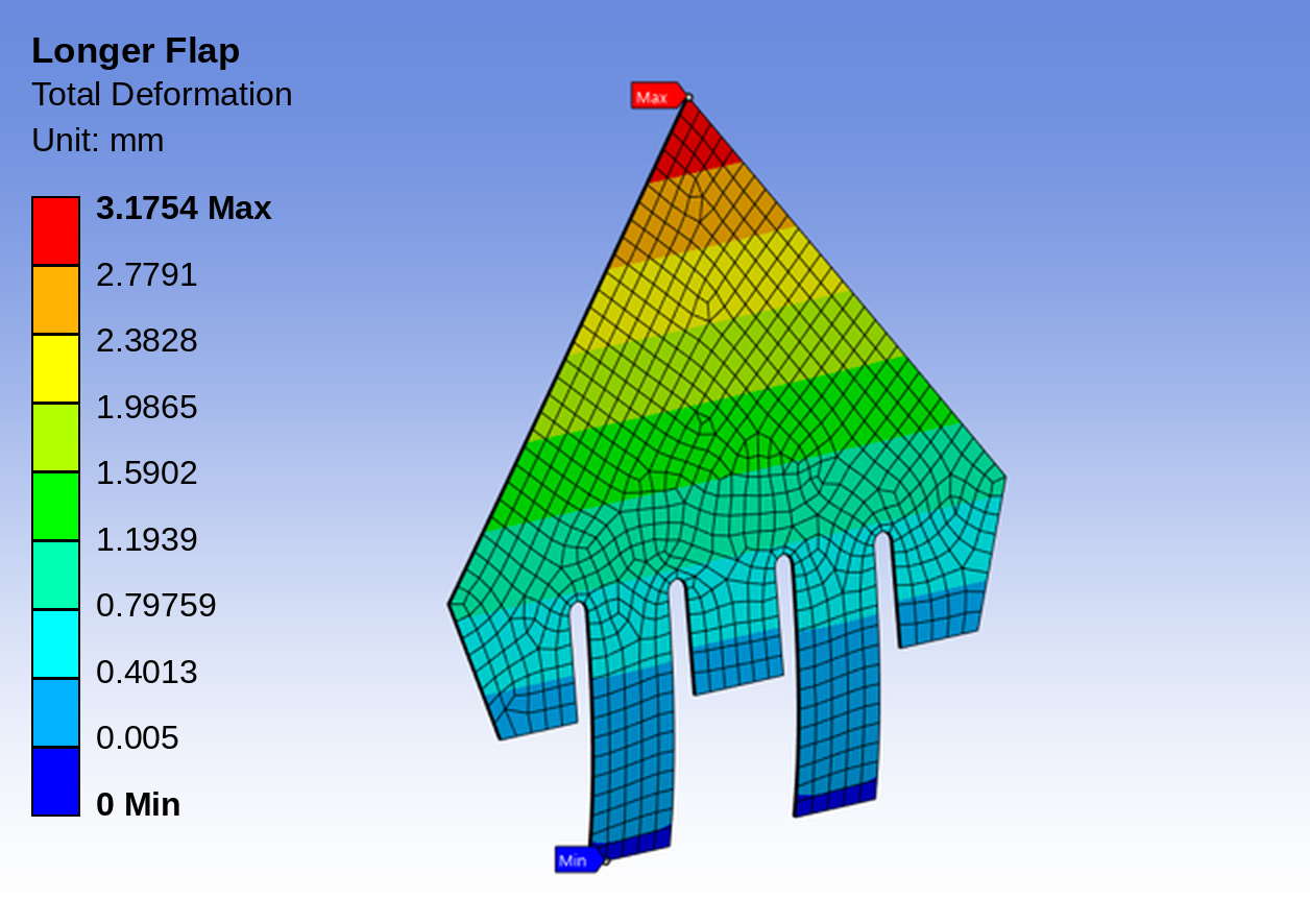
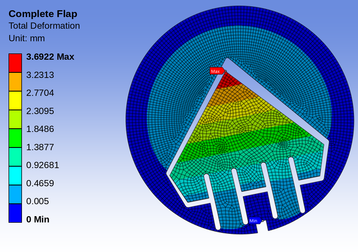
Figure 11: Displacement of the Flap tip at uniform Pressure depending highly on flap base geometry.
Left: Flap cut at bottom of legs, Right: Complete Flap
Flutter Risk and Dynamic Effects
The design variant with one leg showed a tendency toward fluttering behavior in experimental measurements. While Fluid-Structure Interaction simulation can capture such dynamic instabilities, doing so requires transient simulations with fine temporal resolution, which significantly increases computational effort and time. As a result, flutter analysis remains feasible but is highly demanding in terms of time and resources.
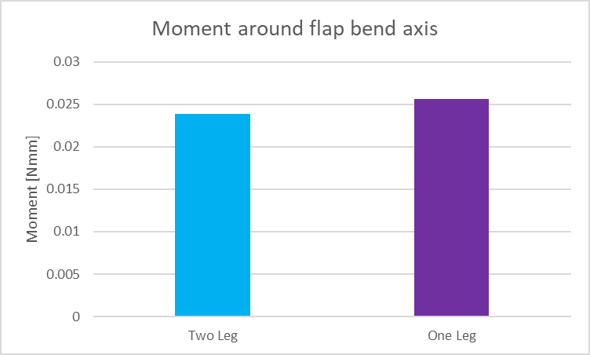
Instead of doing an unsteady FSI simulation for flutter analysis, the moment around the bend axis of the flap can be computed and compared.
Instead of doing an unsteady FSI simulation for flutter analysis, the moment around the bend axis of the flap can be computed and compared. A two-leg design has a lower moment which means that the center of forces is closer to the bend axis assuming the same resultant force acting on the flap. This might be the explanation why this design is less prone to fluttering than the design with one leg.
Impact for Future Development Projects: accelerating the Design Process
The combination of validation FSI simulation and simpler structural simulations enables a more efficient development workflow.
The combination of validated FSI simulation and simpler structural simulations enables a more efficient development workflow.
Full FSI Simulation (High Fidelity)
- Used selectively for validation and critical design points
- Provides deep physical understanding
Simplified Structural Models (Fast Iteration)
- Use uniform pressure assumptions
- Enable rapid comparison of flap geometries
- Support early-stage decision-making
This hybrid approach significantly reduces reliance on:
- Laser-cut or punched flap prototyping
- Additively manufactured prototypes or injection molding iterations with long lead times
Conclusion
Fluid-Structure Interaction simulation provides a powerful framework for understanding and optimizing flow sensors with deformable elements.
While full FSI simulations remain computationally demanding, their ability to accurately replicate real-world behavior makes them invaluable for validation and insight generation. By complementing these models with simplified structural approaches, engineers can significantly accelerate the design process, reduce development risks, and improve product performance.
In many development projects at IMT, physical prototypes are used alongside virtual simulations to evaluate and refine different design concepts.
Deciding whether a complex simulation model or a physical prototype is the more effective next step depends on pragmatic engineering judgment, project constraints, and the specific questions to be answered.
In practice, the combination of numerical simulation and experimental validation delivers the deepest understanding of the product and enables efficient, robust, and application-focused development.

Kaspar Schlegel
Mechanical Expert
Share





More Expert Blog articles
Discover IMT’s engineering expertise and innovative solutions in our Expert Blog. Gain valuable know-how from our experts and explore technology highlights.